Combined
File-Based Processing
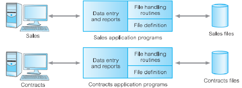
Limitations
- Separation and isolation of data
- Each program maintains its own set of data
- Users of one program ma be unaware of potentially useful data held by other programs
- Duplication of data
- Same data is held by different programs
- Wasted space and potentially different values and/or different formats for the same item
- Data dependence
- File structure is defined in the program code
- Incompatible file formats
- Programs are written in different languages, and so cannot easily access each other’s files
- Fixed queries/proliferation of application programs
- Programs are written to satisfy particular functions
- Any new requirement needs a new program
- No provision for concurrent access
Database
The limitations in a file-based approach leads to database/database management system (DBMS)
Database
- A shared collection of logically related data (and a description of this data), designed to meet the information needs of an organisation
DBMS
- A software system that enables users to define, create, maintain and control access to the database
Database Application Program
- A computer program that interacts with databases by issuing an appropriate request (SQL statement) to the DBMS
History of Database Systems
Advantages of DBMS
- Control of data redundancy
- Data consistency
- More information from the same amount of data
- Sharing of data
- Improved data integrity
- Improved security
- Enforcement of standards
- Economy of scale
- Balance conflicting requirements #what
- Improved data accessibility and responsiveness
- Increased productivity
- Improved maintenance through data independence
- Increased concurrency
- Improved backup and recovery services
Disadvantages of DBMS
- Complexity
- Size
- Cost of DBMS
- There are free ones lol, PostgreSQL
- Additional hardware costs
- Cost of conversion
- Performance
- Higher impact of failure
Summary
- Limitations in file-based systems leads to database approach
- DBMS allows users to interact with databases
- There are many components and roles in database environments
- Before implementing databases, you need to be aware of advantages and disadvantages of DBMSs
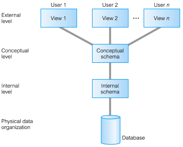
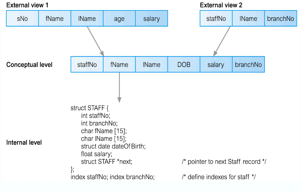
External
- The user, completely independent of the database designer
Conceptual - The schema for the database
- The design of the tables, their relations
- All the SQL that makes the database
Internal
- Where the data is, how to find it and how it is compressed
- The communications between the DBMS and the Database
Data Independence
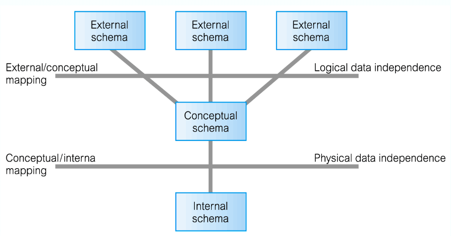
- Allows you to edit the database without needing to change anything in the External Schema
- Unless! you
a column from a table - Then the External Schema will break
Physical Data Independence
- Then the External Schema will break
- Unless! you
- You can modify the Internal Schema massively without needing to change the Conceptual Schema
- If you:
- Move the database to a new storage location (bigger hard drive)
- Rearrange the layout of the files
- Change the hashing algorithm
- Change the compression techniques
- The conceptual level remains unchanged
Database Languages
DDL
- To Create, Update or Delete database objects with,
- Data Definition Language
DML - To Add, Update, Delete or Retrieve data from a database with,
- Data Manipulation Language
Data Models
Model – representation of real-world objects and events, and their associations
Object-Based
Entity-Relationship
Object-Oriented
Semantic, Functional
Record-Based
Relational
Hierarchical
Network
Physical
Functions of a DBMS
- Data Storage, Retrieval, and Updation
- A User-Accessible Catalog
- A catalog is the hierarchy above a schema
- e.g. A catalog is a collection of schema’s, which are collections of tables
- A catalog is the hierarchy above a schema
- Transaction Support
- A unit of work performed within a database
- Generally represents any change in a database
- Concurrency Control Services
- Prevent simultaneous transactions from interfering with each other
- Recovery
- Authorisation
- Support for Data Commutation
- Integrity Services
- Services to Promote Data Independence
- Utility Services
Multi-User DBMS Architectures
Most common: Client-Server Architecture
Client
- Manages the user interface and runs applications
Server - Holds database and DBMS
- Controls data validation and Database access
Flaws - Client requires considerable resources to run effectively (Data processing)
- Significant client-side admin overhead
A 3rd tier is proposed
1 - Client
- Manages user interface
2 - Application Server - Manages data processing and business logic
3 - Database Server - Same as before
Pros - Supports data independence
Relational algebra operations work on one or more relations to define another relation without changing the original relations
- Both operands and results are relations, so output from one operation can become input to another operation
- Five basic operations in relational algebra:
- Selection
- Projection
- Cartesian Product
- Union
- Set Difference
- Rename?
- Three secondary operations (Defined using the basic operations)
- Join
- Intersection
- Division
Selection
For Example: List all staff with a salary > 10,000
Projection
For Example: Produce a list of salaries for all staff, showing only staffNo, fName , lName and salary details
Union
For Example: List all cities where there is either a branch office or a property for rent
Cartesian Product
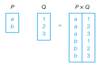
For Example: List the names and comments of all clients who have viewed a property for rent
Intersection
For Example: List all cities where there is both a branch office and at least one property for rent
Set Difference
For Example: List all cities where there is a branch office but no properties for rent
Rename
For Example, Relation Name:
For Example, Attribute Name:
Natural Join
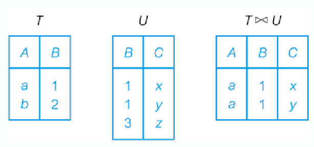
For Example:
Theta Join
- If
only contains equality operations then the term Equijoin is used
For Example: List all students exams where they got above 70%
Semi-Join
- Only the columns of
- Each tuple in
(Left) Outer Join
- Also, if a predicate is given, it becomes the new primary key to be used
%20Outer%20Join.png)
For Example:
(Right) Outer Join
Full Outer Join
Aggregation
For Example:
Grouping
For Example:
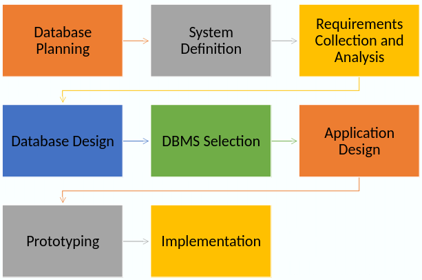
The Life-cycle
Conceptual Database Design
- The process of constructing a model of the data used in an enterprise, independent of all physical considerations
Building the Conceptual Model
- Identify Entities
- Identify Relationships
- Identify and associate Attributes with Entities or Relationships
- Determine Attribute Domains
- Determine Keys
- Consider enhanced modelling
(optional step) - Check model for redundancy
- Validate model against user transactions
- Review data model with user
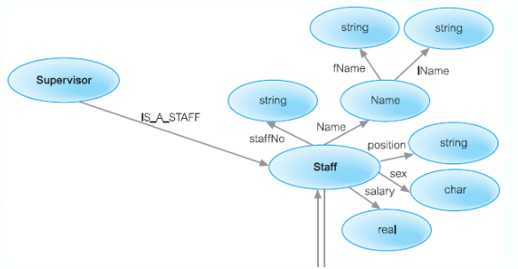
Entity-Relationship Modelling
- Entity-relationship modelling analyses data requirements in a systematic way to help produce a well-designed database
- ER modelling should always be completed before you implement your database
- Everything is modelled in terms of three basic concepts: Entity, Attribute, Relationship
Notations
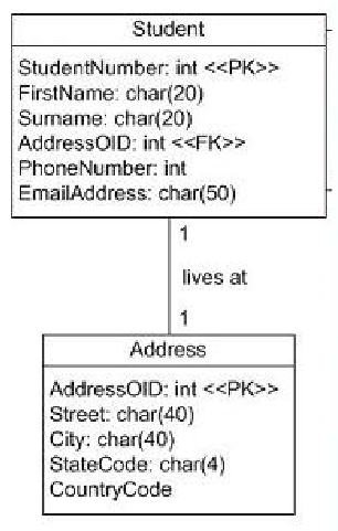
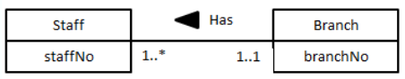
UML (Unified Modelling Language)
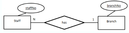
Chen’s Notation
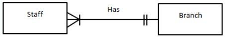
Crow’s Feet Notation
Others
- Bachman Notation, Barker’s Notation, IDEF1X, etc…
Entity
A group of objects with the same properties (Attributes), having an independent existence
- Physical entity (Car, Staff, Product, Influencer)
- Conceptual entity (Timetable, Sale, Viewing, Spending)
- Entity occurrence or instance of an entity
- Uniquely identifiable instance of an entity such as Nigel Ng (Uncle Roger) is an instance of the entity Influencer
Strong Entity: An entity that is not existence-dependent another entity
Weak Entity: An entity that is existence-dependent on another entity
- Uniquely identifiable instance of an entity such as Nigel Ng (Uncle Roger) is an instance of the entity Influencer
Attribute
A property of an entity or a relationship
- Attribute Domain
- A set of allowable values for one or more attributes
- e.g. Age, 1 to 150 years
- Example: An Influencer entity with attributes firstName and lastName
Simple Attribute: An attribute composed of a single component with an independent existence,
e.g. ID
Composite Attribute: An attribute composed of multiple components, each with an independent existence,
e.g. deliveryAddress can be subdivided into Street, City and Postcode
Derived Attribute: An attribute that represents a value that is derivable from a value of a related attribute, or set of attributes, not necessarily in the same entity,
e,g, Age can be calculated from DOB
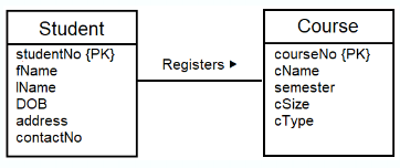
Relationship
Entities take part in relationships.
- Identify relationships from verbs or verb phrases
- A set of meaningful associations among entities
- Shown as a line connecting associated entities together with the name of the relationship
- Example: a student registers a course
Degree of a Relationship
The number of participating entities in a relationship
Unary (degree 1) - One entity
Binary (degree 2) - Two entities
Ternary (degree 3) - Three entities
Quaternary (degree 4) - Four entities
N-ary (degree 5) - n entities
Step 1: Identify Entity (types)
- Examine user’s requirements specification
- Identity nouns or noun phrases,
e.g. Staff Number, Staff Name, Property Number - Look for major objects, such as People, Places or Concepts of Interest, excluding nouns that are Attributes
- Look for objects with an independent existence
- If possible, the users should be involved
- Document entities in a data dictionary
| Entity Name | Description | Aliases | Occurence |
|---|---|---|---|
| Staff | … | Employee | … |
Step 6: Identify Relationships
- Look for verbs or verb phrases
- Determine multiplicity constraints (section 3) of relationships
- Document relationships
| Entity Name | Multiplicity | Relationship | Multiplicity | Entity Name |
|---|---|---|---|---|
| Staff | 0..1 | Manages | 0..100 | PropertyForRent |
| Many-to-Many (*..*) |
||||
| Create a Composite Entity: | ||||
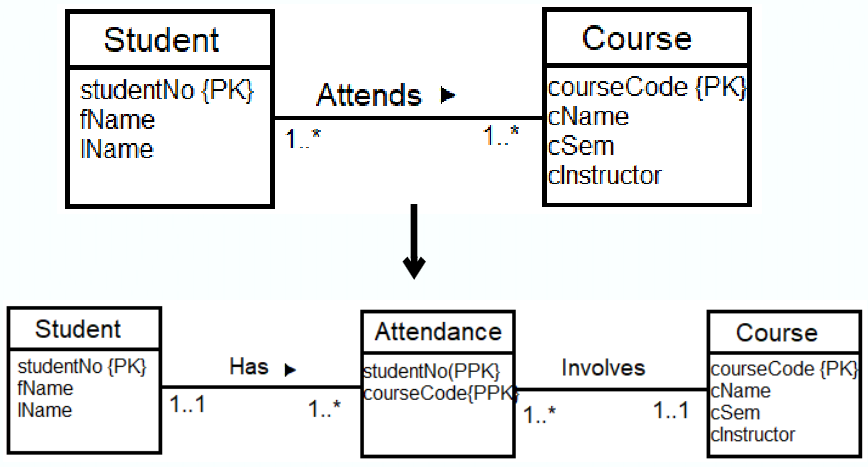 |
Step 3: Identify Attributes
Look for nouns or noun phrases that are a property, quality, identifier, or characteristic of entities or relationships
- Document the attributes in a data dictionary
| Entity Name | Attributes | Description | Data Type & Length | Nulls? | Multi-valued? |
|---|---|---|---|---|---|
| Staff | staffNo … |
… | 5 variable characters | No | No |
Step 5: Determine Keys
Identify the candidate key(s) for an entity and then select the primary key
Some general guideline in choosing a primary key:
- The key with the minimal set of attributes
- The key with values least likely to change
- The Key with the fewest characters or smallest maximum value
- The key that is easiest to use from the user’s point of view
Document the keys
Step 7: Check Model for Redundancy
- Re-examine one-to-one (1..1) relationships
- Merge entities if needed
- Removed redundant relationships
- Between same entities
- Consider time dimensions
- Potential influence in the future
Step 8: Validate Model with User Transactions
- Attempt to perform the operations manually using the model
- Can all transactions be done? If not, there must be a problem with the model
Problems with ER Models
Problems may arise when designing a conceptual data model called connection traps
- Often due to a misinterpretation of the meaning of certain relationships
- Two main types of connection traps are called fan traps and chasm traps
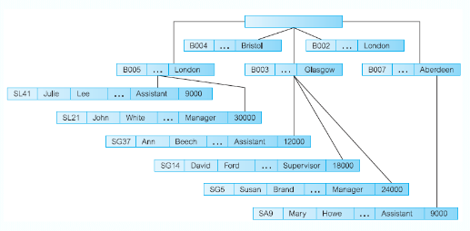
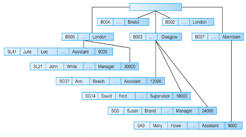
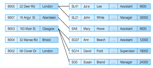
Fan Trap
This is where a model represents a relationship between entity types, but the pathway between certain entity occurrences is ambiguous
- A fan trap may exists where two or more 1:* relationships fan out from the same entity
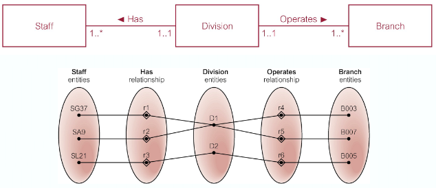
At which branch does staff number SG37 work?
Remove Fan Trap:
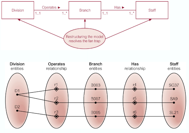
SG37 works at branch B003
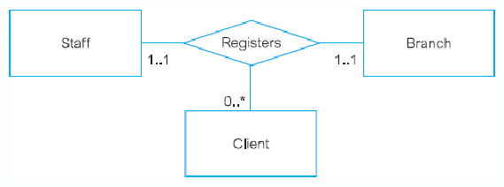
Chasm Trap
This is where a model suggests the existence of a relationship between entity types, but a pathway does not exist between certain entity types
- May occur with relationships with a minimum multiplicity of 0 forming part of the pathway between related entities
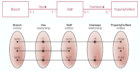
At which branch office is property PA14 available?
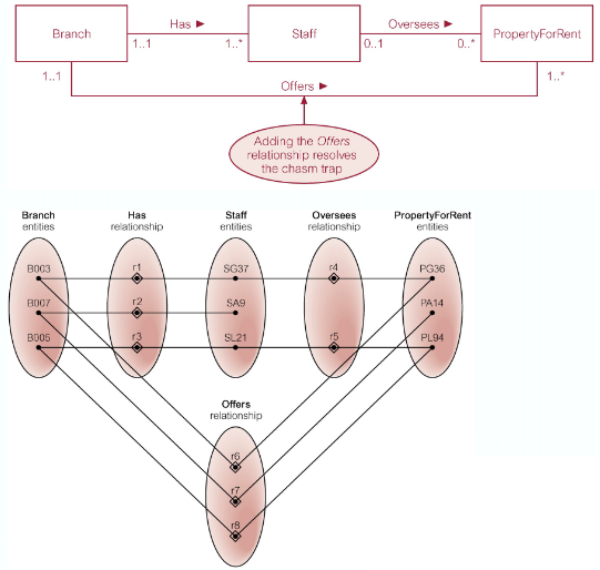
Remove Chasm Trap
Database Design
Conceptual Design:
- See ER-Modelling
Logical Design - The process of constructing a model of the data used in an enterprise based on a specific data model (e.g. relational), but independent of a particular DBMS and other physical considerations
Physical Design - The process of producing a description of the implementation of the database on secondary storage; it describes the base relations, file organisations, and index design use to achieve efficient access to the data, and any associated integrity constraints and security measures
Critical Success Factors in DB Design
- Work interactively with the users!
- Follow a structured methodology throughout
- Employ a data-driven approach
- Incorporate structural and integrity considerations
- Combine conceptualisation, normalisation, and transaction validation techniques
- Use diagrams to represent data models
- Use a Database Design Language (DbDL) to represent additional data semantics
- Build a data dictionary to supplement the data model diagrams
Logical DB Design
Conceptual Model
- Derive Relations
- Validate Relations using normalisation
- Validate relations against user transactions
- Define integrity constraints
- Review logical data model with user
- (optional) Merge logical data models into global model
- Check for future growth
Derive Relations
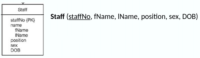
Strong Entities
- For each strong entity in the data model, create a relation that includes all the simple attributes of that entity
- For composite attributes, include only the constituent simple attributes
Weak Entities
- For each weak entity, create a relation with the primary key partially or full derived from each owner entity after all relationships with the owner entities have been mapped
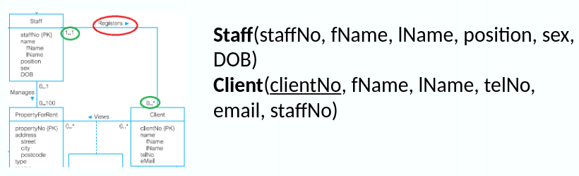
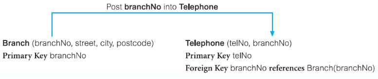
One-to-Many (1:*) Binary Relationships
- For each 1:* binary relationship, the entity on the ‘one side’ is designated as the parent entity and the entity on the ‘many side’ is designated as the child entity. A copy of the primary key attribute(s) of the parent entity is placed in the relation for the child entity as a foreign key
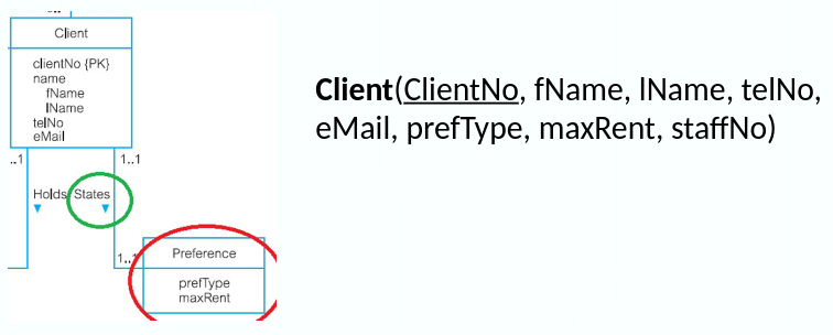
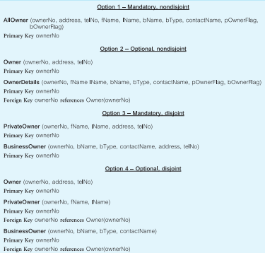
One-to-One (1:1) Binary Relationships
More complex as the cardinality cannot be used to identify to parent and child identities in a relationship
- Instead, the participation constraints are used to decide whether
- To represent the relationship by combining the entities involved into one relation or
- by creating two relations and posting a copy of the primary key from one relation to the other
- Consider the following
- (a) Mandatory participation on both sides
- Combine entities into one relation and choose one of the primary keys of the entity to be primary key and the other as an alternate key
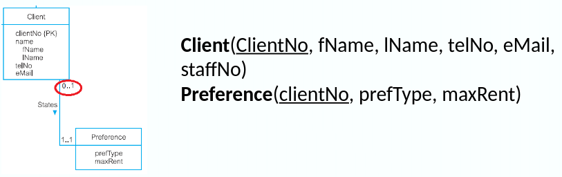
- (b) Mandatory participation on one side
- The entity with optional participation is designated as the parent entity, and the entity with mandatory participation is designated as the child entity.
- A copy of the primary key of the parent entity is places in the relation for the child entity
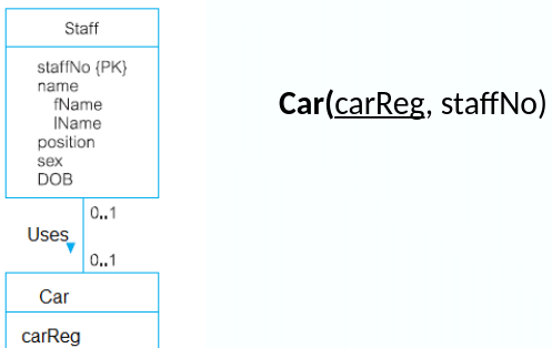
- (c) Optional participation on both sides
- Arbitrary designation of the parent and child entities unless we can find out more about the relationship that can help a decision be made one way or the other
- (a) Mandatory participation on both sides
One-to-One (1:1) Recursive Relationships
For 1:1 recursive relationships, follow the same rules for participation as in a 1:1 relationship
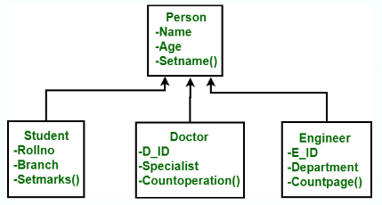
Superclass/Subclass Relationships
Identify superclass entity as the parent and the subclass entity as the child
There are options to represent such relationships depending on participation and disjoint constraints
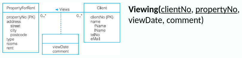
Many-to-Many (*:*) Binary Relationships
Create a relation for the relationship with all the attributes of the relationship, with a copy of the primary key of the participating entities as foreign keys. These foreign keys will also form the primary key of the new relation
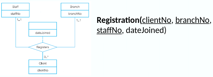
Complex Relationships
Create a relation to represent the relationship. Copy the primary key of the participating entities as foreign keys.
Any foreign keys that represent a ‘many’ relationship (for example, 1..*, 0..*) generally will also form the primary key of this new relation
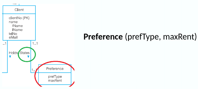
Multi-Valued Attributes
Create a new relation for the multi-valued attribute with the primary key of the entity as a foreign key.
Unless the multi-valued attribute is itself an alternate key of the entity, the primary key of the new relation is the combination of the multi-valued attribute and the primary key of the entity
Validate Relations with Normalisation
To validate the relations in the logical data model using normalisation to ensure that the set of relations has a minimal yet sufficient number of attributes necessary to support the data requirements of the enterprise
Validate Relations Against User Transactions
Attempt to perform the operations manually using the relations, and the primary key/foreign key links in the relations
If we are unable to perform a transaction manually, there must be a problem with the data model that must be resolved
Check Integrity Constraints
Identifying:
- Required data
- Attribute domain constraints
- Multiplicity
- Entity integrity
- Referential integrity
- General constraints
Referential integrity considerations when a tuple in parent relation is deleted: - NO ACTION, CASCADE, SET NULL, SET DEFAULT, NO CHECK
Step 5 – Step 7
Review the Logical Data Model with the User
- Review the logical data model with the users to ensure that they consider the model to be a true representation of the data requirements of the enterprise
Merge Logical Data Models into Global Model (Optional Step) - To merge logical data models into a single global logical data model that represents all user views of a database
Check for Future Growth - To determine whether there are any significant changes likely in the foreseeable future and to assess whether the logical data model can accommodate these changes
Physical DB Design
Logical Model
- Translate logical data model for target DBMS
- Design file organisations and indexes
- Design user views
- Design security mechanisms
- Consider the introduction of controlled redundency
- Monitor and tune the operational system
Translate Logical Data Model for Target DBMS
Design Base Relations
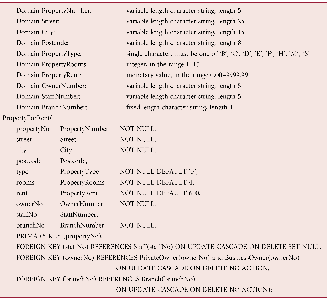
From the data dictionary, produce the DbDL to define domains, default values, and null indicators
Design Representation of Derived Data
To decide how to represent any derived data present in the logical data model in the target DBMS
- Examine the logical data model and data dictionary, then produce a list of all the derived attributes
- Each derived attribute can be stored in the database or calculated every time it is needed
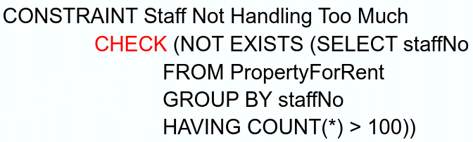
Design General Constraints
To design the general constraints for the target DBMS - Some DBMS provide more facilities than others for defining enterprise constraints, Example:
Design File Organisations & Indexes
To determine [optimal file organisations to store the base relations in and] the indexes that are required to achieve acceptable performance; that is, the way in which relations and tuples will be held on secondary storage
Analyse Transactions
To understand the functionality of the transactions that will run on the database and to analyse the import transactions
- Attempt to identify performance criteria, such as:
- Transactions that run frequently and will have a significant impact on performance
- Transactions that are critical to the business
- Times during the day/week when there will be a high demand on the database (called the peak load)
Choose file Organisations
To determine an efficient file organisation for each base relation
- File organisations such as
- Heap
- Hash
- Indexed Sequential Access Method (ISAM)
- Some DBMSs may not allow selection of file organisations
Choose Indexes
To determine whether adding indexes will improve the performance of the system
- One approach is to keep tuples unordered and create as many secondary indexes as necessary
- Another approach is to order tuples in the relation by specifying a primary or clustering index
Estimate Disk Space Requirements
yeah
Design User Views
To design the user views that were identified during the Requirements Collection and Analysis stage of the database system development life-cycle
Design Security Measures
To design the security measures for the database as specified by the users
Consider the Introduction of Controlled Redundancy
- To determine whether introducing redundancy in a controlled manner by relaxing the normalisation rules will improve the performance of the system
Monitor and Tune the Operational System
- To monitor the operational system and improve the performance of the system to correct inappropriate design decisions or reflect changing requirements
Why Normalisation?
To prevent data redundancy
- Minimal number of attributes required
- Attributes with a close logical relationship in the same relation
- Minimal redundancy
Less storage
The ‘Approaches’
Approach 1: Use normalisation as a bottom-up technique to create a set of relations
Approach 2: Use normalisation as a validation technique to check structure of relations
Approach 1
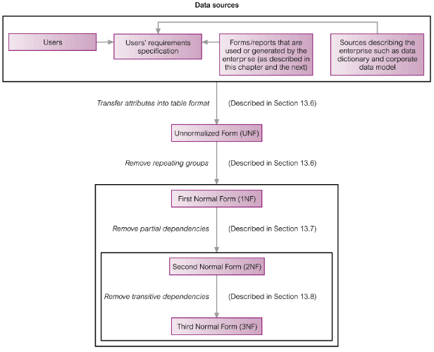
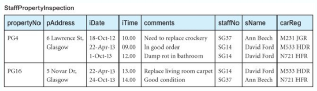
Unnormalised Form (UNF)
A relation that contains one/more repeating groups
To create an unnormalised relation
- Transform the data from the information source (e.g. a form) into table format with columns and rows
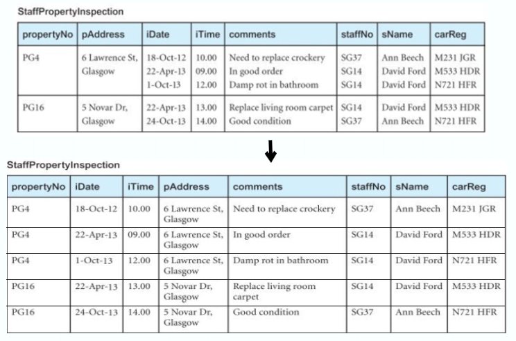
First Normal Form (1NF)
A relation in which the intersection of each row and column contains one and only one value
UNF
- Nominate an attribute or group of attributes to act as the primary key for the unnormalised table
- Identify the repeating group(s) in the unnormalised table which repeats for the key attribute(s)
- Remove the repeating group by
- Entering appropriate data into the empty columns of rows containing the repeating data (‘flattening’ the table)
- Or, by placing the repeating data along with a copy of the original key attribute(s) into a separate relation
Functional Dependency (FD)
If
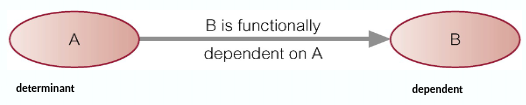
Full Functional Dependency: The dependent is functionally dependent on the determinant, but not any proper subset of the determinant
Partial & Transitive Dependencies
Partial Dependency
, staffName warehouseNo, warehouseAddress, sales warehouseNo, warehouseAddress, sales
Here warehouseNo, etc are partially dependent on, staffName’ as they don’t really need staffName
Transitive Dependency- staffNo
, warehouseAddress, sales warehouseAddress
Here warehouseAddress is transitively dependent on staffNo
Identify FD?- Users and/or documentation
- Common sense
- Sample data
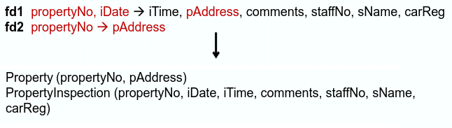
Second Normal Form (2NF)
A relation that is in 1NF and every non-primary-key attribute is fully functionally dependent on the primary key/(any candidate key?)
1NF
- Identify the functional dependencies in the relation
- Identify the primary key for the 1NF relation
- If the partial dependencies exist on the primary key, remove them by placing them in a new relation along with a copy of their determinant
Third Normal Form (3NF)
- A relation that is in 1NF and 2NF and in which no non-primary-key attribute is transitively dependent on the primary key/(any candidate key?)
2NF3NF - Identify the primary key in the 2NF relation
- Identify functional dependencies in the relation
If transitive dependencies exist on the primary key, remove them by placing them in a new relation along with a copy of their determinant
Boycee-Codd Normal Form (BCNF)
A relation is in BCNF if and only if every determinant is a candidate key
- Every relation in BCNF is also in 3NF. However, a relation in 3NF is not necessarily in BCNF
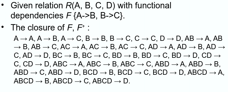
More Function Dependencies?
The complete set of functional dependencies for a given relation can be very large
The set of all functional dependencies that are implied by a given set of functional dependencies F is called the closure of F, written
- Armstrong’s axioms is used to find
Interference Rules for FDs
A set of interference rules, called Armstrong’s axioms, specifies how new functional dependencies can be inferred from given ones
- Let
, , and be subsets of the attributes of the relation . Armstrong’s axioms are as follows:
- Reflexivity
Ifis a subset of , then - Augmentation
If, then - Transitivity
Ifand , then
Further rules can be derived from the first three rules. Letbe another subset of the attributes of relation , then - Self-determination
- Decomposition
Ifthen and - Union
Ifand , then - Composition
Ifand then
Example?:
Closure
The closure of attribute set
Given relation
Closure of attributes:
- etc…
Finding Candidate Keys with Attribute Closure
Given relation
Closure of attributes
Since a single attribute is unable to determine all the attributes on its own, we combine two or more attributes to determine the candidate keys
Minimal Sets of FDs
A set of functional dependencies
- Every dependency in
has a single attribute on its right-hand side (C1) - We cannot replace any dependency
in with dependency , where is a proper subset of and still have a set of dependencies that is equivalent to (C2) - We cannot remove any dependency from
and still have a set of dependencies that is equivalent to (C3)
– Note that there can be several minimal covers for a set of functional dependencies
Why do we care?
Data is valuable! it must be strictly controlled and managed, as with any corporate resource
The DBMS must ensure that the database is secure
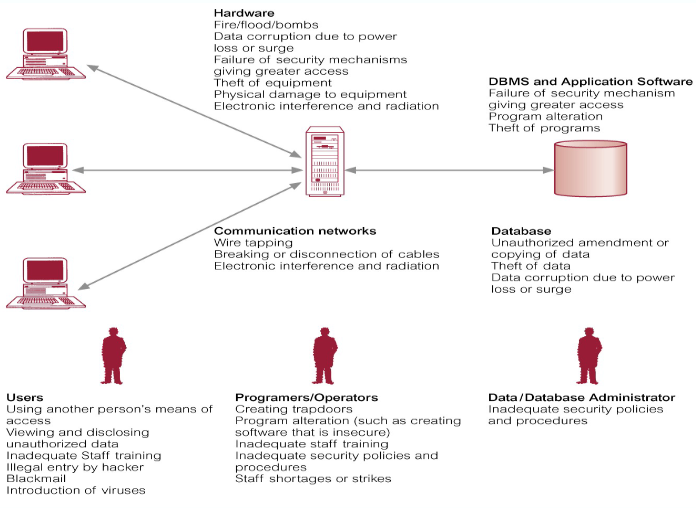
Database security covers not only DBMS, but also its environment,
- Hardware, software (DBMS, application software, OS, etc…), people data, procedures
Security
- Confidentiality – Secrecy over data
- Integrity – Protect against invalid or corrupted data
- Availability – Data or systems available to legitimate users
- Authentication
- Non-repudiation
CIA of security

Database Security
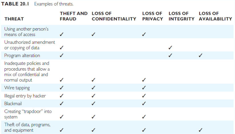
Protect against:
- Loss of confidentiality on the secrecy over data critical to the organisation
- Loss of privacy on data about individuals
- Loss of integrity with invalid or corrupted data
- Loss of availability as data or systems are unavailable to legitimate users
- Theft and fraud of data, identity, programs, or hardware
Threat – Any situation or event, whether intentional or unintentional, that will adversely affect a system and consequently an organisation - Need to consider not only the data held in a database but the whole ecosystem
- Failure to protect could lead to loss of confidentiality, loss of competitiveness, loss of privacy, legal action, corrupted data, financial loss, etc…
Countermeasures: - Physical Controls
- Procedures
- Computer-Based Controls
Computer-Based Controls
Authorisation
The granting of a right or privilege, which enables a subject to legitimately have access to a system or a system’s object
- Involves authentication which determines whether a user is, who he or she claims to be
- A common authentication method is through the user of a password (we recommend a passphrase)
- How strong is your password
- Other methods? Multi-factor authentication such as Duo
Access Control
Methods used to enforce authorisation
-
Based on the granting and revoking privileges
-
A privilege allows a user to create or access (that is read, write, or modify) some database object (such as a relation, view, or index) or to run certain DBMS utilities
-
Privileges are granted to users to accomplish the tasks required for their jobs
-
Most DBMSs provide an approach called Discretionary Access Control (DAC)
-
SQL standard supports DAC through the GRANT and REVOKE commands*
-
The GRANT command gives privileges to users, and the REVOKE command takes away privileges
*SQLite does not support GRANT and REVOKE.
Access control is through the API at the application level
Examples:
GRANT SELECT, UPDATE (salary)
ON Staff
TO Personnel, Director;

GRANT SELECT
ON Branch
TO PUBLIC
Views
Hiding parts of the database from certain users
Backup & Recovery
Backup data at regular intervals to a secure location
Journaling
- Keep and maintain a log file (or journal) of all changes made to the database to enable effective recovery in the event of failure
Integrity Constraints
Through enforcing integrity constraints
- Domain constraints
- Entity integrity
- Referential integrity
Encryption
- Applying an encryption algorithm on data
- The encoding of the data by a special algorithm that renders the data unreadable by any program without the decryption key
- Four components: encryption key, encryption algorithm, decryption key, decryption algorithm
- Symmetric encryption – same key
- Caesar cipher, Vigenere, DES, 3DES, Blowfish, AES, ChaCha - Asymmetric encryption – different key
- RSA (Rivest–Shamir–Adleman), Elliptical Curve, Cryptography (ECC), Diffie-Hellman
Asymmetric Encryption:
A set of keys: secrete/private key, public key
Challenges:- Key generation
- Authentication of the public key
Public key infrastructure (PKI)
Usage: - Public key encryption
- Digital signatures
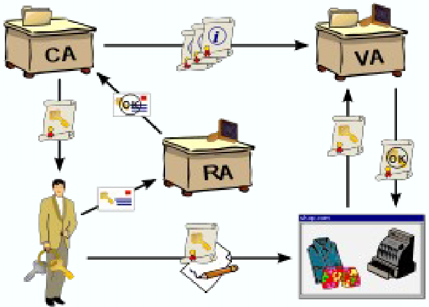
Public-key Infrastructure (PKI)
A set of roles, policies, hardware, software and procedures needed to create, manage, use, store, and revoke digital certificates and manage public-key encryption
CA - Certificate Authority
- Creates, issues and manages the PKs as a trusted third party
RA - Registration Authority - Ensures an authorised identity is requesting a certificate
VA - Validation Authority - Authenticates and validates issued certificates
Hashing
Process of taking a group of characters, apply a hash function to it, to generate a fixed length hash value
- One way encryption as the hashes are irreversible
Examples: MD5, SHA, SHA-2, SHA-3, DSA, Whirlpool, BLAKE, BLAKE-2, BLAKE-3
Usage:- Verify integrity of files and messages
- Digital signatures
- Password verification
DBMSs and Web Security
Internet communication relies on TCP/IP as the underlying protocol. However, TCP/IP and HTTP were not designed with security in mind. Without special software, all internet traffic travels ‘in the clear’ and anyone who monitors traffic can read it
You must ensure transmission over the Internet is:
- Inaccessible to anyone but the send and receiver (privacy/confidentiality?)
- Not changed during transmission (integrity)
- Receiver can be sure it came from the sender (authenticity)
- Sender can be sure receiver is genuine (non-fabrication)
- Sender cannot deny they sent it (non-repudiation)
Security measures include:
- Proxy servers
- Firewalls
- Message digest algorithms and digital signatures
- Digital certificates
- Kerberos
- Secure Sockets Layer (SSL) and Secure HTTP (S-HTTP)
- Secure Electronic Transactions (SET) and Secure Transaction Technology (SST)
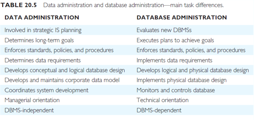
Data & DB Administration
Data administrator (DA)
- Managing data resources, including database planning, development, maintenance of standards, policies, procedures, and conceptual and logical database design
Database administrator (DBA) - Application/physical database design to operational management including setting security and integrity control, and monitoring system performance
Data Administration Tasks
- Selecting appropriate productivity tasks
- Assisting in the development of the corporate IT/IS and enterprise strategies
- Undertaking feasibility studies and planning for database development
- Developing a corporate data model
- Determining the organisation’s data requirements
- Setting data collection standards & data formats
- Estimating volumes of data and likely growth
- Determining patterns and frequencies of data usage
- Determining data access requirements and safeguards for both legal and enterprise requirements
- Undertaking conceptual and logical database design
- Liaising with other parties involved with the database to ensure all requirements are met.
- Educating users on data standards & legal responsibilities
- Keeping up to date with IT/IS and enterprise developments
- Ensuring the documentation is up to data and complete
- Managing the data dictionary
- Liasing with users to determine new requirements and to resolve difficulties over data access or performance
- Developing a security policy
Database Administration Tasks
- Evaluating and selecting DBMS products
- Physical database designs and implementation on target DBMS
- Defining security and integrity constraints
- Liasing with database application developers
- Developing test strategies
- Training users
- “Signing off” on the implemented database system
- Monitoring system performance and tuning the database
- Performing routine backups
- Ensuring recovery mechanisms & procedures are in place
- Ensuring that documentation is complete
- Keeping software & hardware up to date, including cost
Why do we care?
- How many users/database operations are accessing the database system at one time
- How sure are you that there won’t be any incidents affecting the data in the database? e.g. system crash, media failure, error in program? How about sabotage?
- DBMS provides concurrency control and database recovery
Transaction Support
What is a transaction?
-
An action, or series of actions, carried out by a user or application, which reads or updates contents of a database
-
Logical unit of work on the database
-
An/The? Application program is a series of transactions with non-database processing in between
-
Transforms the database from one consistent state to another, although consistency may be violated during transaction
-
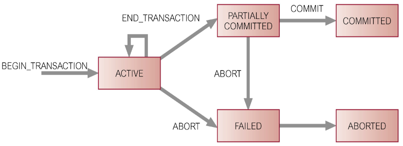
Can have one or two outcomes:
- Success – the transaction commits and the database reaches a new consistent state
- Failure – the transaction aborts, and the database must be restored to a consistent state before it is started
- Such a transaction is rolled back or undone
-
A committed transaction cannot be aborted
-
An aborted transaction that is rolled back can be restarted later
Properties of Transactions
There are four basic (ACID) properties that define a transaction:
- Atomicity – ‘All or nothing’ property
- Consistency – Must transform the database from one consistent state to another
- Isolation – Partial effects of incomplete transactions should not be visible to other transactions
- Durability – Effects of a committed transaction are permanent and must not be lost because of later
Concurrency Control
The process of managing simultaneous operations on the database without having them interfere with one another
- Prevents interference when two or more users are accessing database simultaneously and at least one is updating data
- Although two transactions may be correct in themselves, interleaving of operations may produce an incorrect result
Need for Concurrency Control
Three examples of potential problems caused by concurrency: - Lost update problem
- Uncommitted dependency problem
- Inconsistent analysis problem
Lost Update Problems
A successfully completed update is overridden by another user
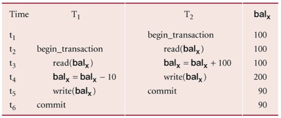
- Loss of
Uncommitted Dependency Problem
Occurs when one transaction can see intermediate results of another transaction before it has committed
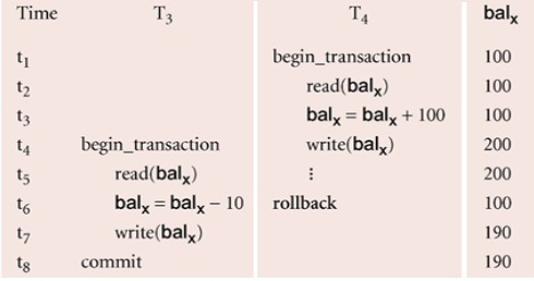
- Problem avoided by preventing
Inconsistent Analysis Problems
Occurs when a transaction reads several values but a second transaction updates some of them during the execution of the first
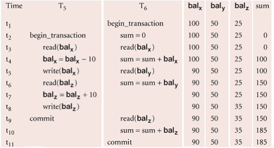
- Problem avoided by preventing
Serialisability
The objective of a concurrency control protocol is to schedule non-interfering transactions
- Serialisability as a means of helping to identify those executions of transactions that are guaranteed to ensure consistency, as if the transactions are run in serial execution
Why all these troubles? Recovery! - If a transaction in a schedule fails, it should be undone
- The DBMS does not test for serialisability of a schedule as the interleaving of operations is determined by the OS
- DBMS
concurrency control techniques to achieve serialisability
Concurrency Control Techniques
Two basic concurrency control techniques
- Locking
- Time-stamping
Both are conservative approaches: delay transactions in case they conflict with other transactions
Optimistic methods assume conflict is rare and only check for conflicts at commit
Locking
Transactions use locks to deny access to other transactions and to therefore prevent incorrect updates
Two types
- Shared lock for reading a data item
- Exclusive lock for both reading & writing a data item
Reads cannot conflict, so more than one transaction can hold shared locks simultaneously on the same item
Exclusive lock gives a transaction exclusive access to that item
Some systems allow transactions to upgrade a shared lock to an exclusive lock, or downgrade an exclusive lock to a shared lock
Locks are used in the following way:
- Any transaction that need to access a data item must first lock the item
- If the item is not already locked by another transaction, the lock will be granted
- If the item is locked, the DBMS determines whether the request is compatible with the existing lock. If a shared lock is requested on an item with a shared lock, the request will be granted; otherwise, the transaction must wait until the existing lock is released
- A transaction continues to hold a lock until it explicitly release it. It is only when the exclusive lock has been released that the effects of the write operation will be made visible to other transactions
Two-Phase Locking (2PL)
A transaction follows the 2PL protocol if all locking operations precede the first unlock operations in the transaction
Two phases for the transaction:
- Growing Phase – acquires all locks but cannot release any locks
- Shrinking Phase – releases the locks but cannot acquire any new locks
Cascading Rollback
If every transaction in a schedule follows 2PL, the schedule is serialisable
- However, problems can occur with the interpretation of when locks can be released
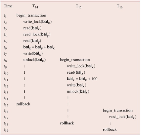
aborts, since is dependent of , must also be rolled back. Since is dependent on , it too must be rolled back
To prevent this with 2PL, you can: - Rigorous 2PL
Leave the release of all locks until the end of the transaction - Strict 2PL
Hold only the exclusive locks until the end of the transaction
Deadlock
An impasse that may result when two (or more) transactions are each waiting for locks held by the other to be released
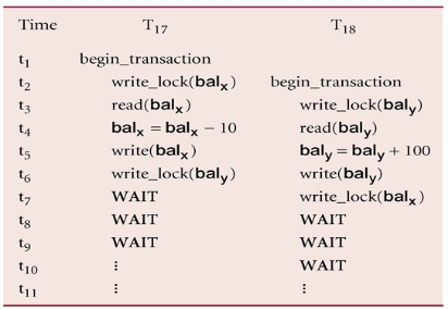
There is only one way to break a deadlock: Abort all but one of the transactions
A deadlock should be transparent to the user, so the DBMS should restart the transaction(s)
However, in practice the DBMS cannot restart the aborted transaction since it is unaware of transaction logic even if it was aware of the transaction history (unless there is no user input in the transaction or the input is not a function of the database state)
Three general techniques for handling a deadlock:
- Timeouts
- A transaction that requests a lock will only wait for a system defined period of time
- If the lock has not been granted within this period, the lock request times out
- In this case, the DBMS assumes the transaction may be deadlocked, even though it may not be, and it aborts and automatically restarts the transaction
- Deadlock prevention
- The DBMS looks ahead to see if the transaction would cause a deadlock and never allows a deadlock to occur
Deadlock detection and recovery
The DBMS allows the deadlock to occur but recognises it and breaks it
- The DBMS looks ahead to see if the transaction would cause a deadlock and never allows a deadlock to occur
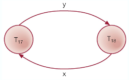
- Usually handled by the construction of a wait-for graph (WFG) showing transaction dependencies
- Create a node for each transaction
- Create edge
if if waiting to lock an item locked by
- A deadlock exists if and only if the WFG contains a cycle
Recovery
There are several issues: - Choice of the deadlock victim
- How long has the transaction been running?
- How many data items have been updated?
- How many data items still need to be updated?
- How far to rollback a transaction?
- Avoiding starvation
- Don’t make the same transaction a victim every time!
Time-stamping
A different approach to locking, with timestamps
- Transactions are ordered globally so that older transactions will smaller timestamps, get priority in the event of conflict
- Conflict is resolved by rolling back and restarting the transaction. No locks so no deadlock
- Time-stamp
- A unique identifier that indicates the relative starting time of a transaction
- Generated by using the system clock, or a logical counter
- A read/write will proceed only if the last update on that data item was carried out by an older transaction
- Otherwise, the transaction requesting the read/write is restarted and given a new timestamp
- Also timestamps for data items:
- read_timestamp – The timestamp of the last transaction to read the item
- write_timestamp – The timestamp of the last transaction to write to the item
Basic Timestamp Ordering
Consider a transaction
is already updated by a younger (later) transaction - The transaction must be aborted and restarted with a new timestamp
- Otherwise, update
Consider a transaction
is already read by a younger transaction - Roll back the transaction and restart it using a later timestamp
is already written by a younger transaction - Roll back the transaction and restart it using a later timestamp
- Otherwise update
Strict time-stamping…
When writing or reading, the transaction must also wait for the last transaction to write to the data item to abort/commit to avoid a cascading rollback
Thomas’ Write Rule
A variation to the basic timestamp ordering protocol that increase concurrency by relaxing strict serialisability
- Thomas’ write rule is that the write can safely be ignored – ignore obsolete write rules
- When the current transaction wants to update a value that has been updated by a younger transaction, that write operation can be ignored and the current transaction does not need to be aborted
Optimistic Techniques
In some environments, conflicts are rare and it is more efficient to proceed without delays
- Checking for conflict before commit
- If there is a conflict, the transaction must be rolled back and restarted
- Three phases:
- Read
- Validation
- Write
Read Phase
Extends from the start until immediately before the commit
- The transaction reads the values from the database and stores them in local variables. Updates are applied to a local copy of the data
Validation Phase
After the read phase,
For a read-only transaction, it checks that the data it read is still the same values. If no interference, the transaction is committed, otherwise it is aborted and restarted
- For an update transaction, it checks whether the transaction leaves the database in a consistent state (adheres to rules, constraints, and integrity requirements), with serialisability maintained
Each transaction
- The start of its execution,
- The start of its validation phase,
- Its finish time,
Given transactionat and transaction at with , to pass the validation test, either:
, or , and - The set of data items written by
are not the ones read by ; and
- The set of data items written by
Write Phase
After a successful validation phase for an update transaction, the updates made to the local copy are applied to the database
Granularity of Data Items
The size of data items chosen as the unit of protection by the concurrency control protocol
Ranging from coarse to fine:
- The entire database
- A file (relation)
- A page
- A unit of predetermined size (typically 4KB, 8KB, 16KB or more)
- A record (tuple)
- A field value of a record
Trade-off: - Coarser, the lower the degree of concurrency
- Finer, more locking information than is needed is stored
The best item size depends on the types of transactions
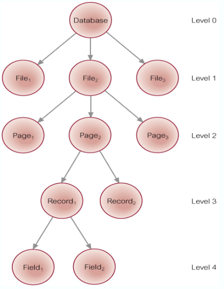
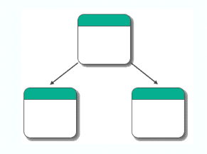
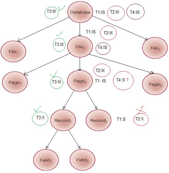
Hierarchy of Granularity
When a node is locked, all its descendants are also locked
- The DBMS should check the hierarchical path before granting a lock
- To reduce searching involved in locating locks, an intention lock could be used to lock all ancestors of a locked node
- Intention locks can be read/write.
Applied top-down, released bottom-up
- Intention locks can be read/write.
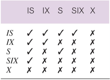
Multiple-Granularity Locking
Intention Shared (IS): explicit locking at a lower level of the tree but only with shared locks
Intention Exclusive (IX): explicit locking at a lower level with exclusive or shared locks
Shared and Intention Exclusive (SIX): the sub tree rooted by that node is locked explicitly in shared mode and explicit locking is being done at a lower level with exclusive mode locks
4 Transactions
Types of Failures
System Crashes: due to hardware/software errors, loss in main memory
Media Failure: such as head crashes or unreadable media, resulting in a loss of parts of secondary storage
Application Software Errors: such as logical errors
Natural Physical Disasters: such as fires, floods, etc…
Carelessness or Unintentional Destruction of Data or Facilities
Sabotage: intentional corruption/destruction
Transactions and Recovery
Transactions represent the basic unit of recovery
- Recovery manager responsible for atomicity and durability
- If failure occurs between a commit and the database buffers being flushed to secondary storage then, to ensure durability, recovery manager has to redo (roll-forward) the transaction’s updates
- If the transaction had not committed at failure time, recovery manager has to undo (rollback) any effects of that transaction for atomicity
Recovery Facilities
The DBMS should provide the following facilities to assist with recovery:
- Backup Mechanism – which make periodic backup copies of the database
- Logging Facilities – which keep track of the current state of the transactions and database changes
- Checkpoint Facility – which enables updates to the database in progress to be made permanent
- Recovery Manager – which allows the DBMS to restore the database to a consistent state following a failure
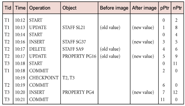
Log File
Contains information about all updates to the database:
- Transaction records
- Checkpoint records
Often used for other purposes (for example, auditing)
- Log file may be duplexed or triplexed (2 or 3 copies)
- The log file is sometimes split into two separate random-access files
- Potential bottleneck; critical in determining overall performance
Checkpointing
- Checkpoint – the point of synchronisation between database and log file. All buffers are force-written to secondary storage
- A checkpoint record is created containing identifiers of all active transactions
- When failure occurs, redo all transactions that committed since the checkpoint and undo all transactions active the time of the crash
Recovery Techniques
If the database has been damaged:
- Need to restore the last backup copy of the database and reapply updates of the committed transactions using the log file
If the database is only inconsistent: - Need to undo all changes that caused inconsistency. May also need to redo some transactions to ensure the updates reach secondary storage
- Do not need the backup, but can restore the database using before- and after-images in the log file
- Thee main recovery techniques:
- Deferred update – till commit
- Immediate update – immediately
- Shadow Paging – two pages